I. GIỚI THIỆU
Chương trình thực hiện giao tiếp I2C giữa PIC 16F877A và IC DS1307 để cài đặt thời gian, đọc thời gian từ DS1307, hiển thị lên LCD, truyền qua RS232.
Với LCD, chương trình sẽ đọc dữ liệu DS1307 và cập nhật LCD liên tục, còn khi truyền lên máy tính sẽ dựa vào ngắt RB0 đưa vào từ xung 1Hz của DS1307, tức là mỗi 1s sẽ truyền dữ liệu 1 lần.
Trong chương trình có sử dụng các thư viện: lcd_lib_4bit.c, ds1307.c.
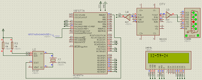
II.Sơ đồ nguyên lý mô phỏng trên Proteus:
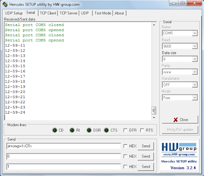
Truyền lên máy tính bằng hyper terminal:
III.Code chính:
#include "16f877a.h"
#include "def_877a.h"

#device *=16 ADC=10
#use delay(clock=20000000)
#FUSES NOWDT, HS, NOPUT, NOPROTECT, NODEBUG, NOBROWNOUT, NOLVP, NOCPD, NOWRT
#use i2c(Master, sda = PIN_C4, scl=PIN_C3)
#use rs232(baud=9600,parity=N,xmit=PIN_C6,rcv=PIN_C7,bits=8)

#include "lcd_lib_4bit.c"
#include "ds1307.c"

#define Slave_add 0x68
#define Read 1
#define Write 0

void send(int8 a);

int8 sec,min,hrs,day,month,yr,dow;

//ngat o chan RB0: Truyen len cong RS232
#int_EXT
void EXT_isr(void) //moi 1s truyen len may tinh 1 lan
{
   ds1307_get_date(day,month,yr,dow);
   ds1307_get_time(hrs,min,sec);
   send(hrs);
   putc(45);
   send(min);
   putc(45);
   send(sec);
   putc(10);
   return;
}
void main()
{
   enable_interrupts(INT_EXT);//cho phep ngat RB0
   ext_int_edge(0,H_TO_L);//dat suon ngat
   enable_interrupts(GLOBAL);//cho phep ngat toan cuc

   LCD_init(); //Khoi tao LCD.
   delay_ms(10);
   ds1307_init();// khoi tao DS1307, tao xung 1Hz o chan 7 DS1307.
   // Set date : 12-4-2012
   // Set time : thu 5 - 12 gio, 59 phút 10 giây
   ds1307_set_date_time(12,4,12,5,12,59,10);

   while(1)
   {
      ds1307_get_date(day,month,yr,dow);
      ds1307_get_time(hrs,min,sec);

      //Truyen len LCD
      //o day chi hien gio, phut, giay. cac thong tin khac thuc hien tuong tu.
      LCD_PutCmd(0x80);
      LCD_PutChar(hrs/10+48);
      LCD_PutChar(hrs%10+48);
      LCD_PutChar(45);
      LCD_PutChar(min/10+48);
      LCD_PutChar(min%10+48);
      LCD_PutChar(45);
      LCD_PutChar(sec/10+48);
      LCD_PutChar(sec%10+48);
   }
}
void send(int8 a)
{
    if(a<10)
     {
         putc(a+48);
     }
     if(a>9&&a<100)
     {
          unsigned char c=a/10;
          unsigned char d=a%10;
          putc(c+48);
          putc(d+48);
     }
     if(a>99)
     {
          unsigned char t=a/100;
          unsigned char c=a/10-10*t;
          unsigned char d=a%10;
          putc(t+48);
          putc(c+48);
          putc(d+48);
     }
}
Thư viện lcd_lib_4bit.c:
#include <stddef.h>

#define LCD_RS          PIN_D2
//#define LCD_RW          PIN_A1
#define LCD_EN          PIN_D3

#define LCD_D4          PIN_D4
#define LCD_D5          PIN_D5
#define LCD_D6          PIN_D6
#define LCD_D7          PIN_D7

// misc display defines-
#define Line_1          0x80
#define Line_2          0xC0
#define Clear_Scr       0x01

// prototype statements
#separate void LCD_Init ( void );// ham khoi tao LCD
#separate void LCD_SetPosition ( unsigned int cX );//Thiet lap vi tri con tro
#separate void LCD_PutChar ( unsigned int cX );// Ham viet1kitu/1chuoi len LCD
#separate void LCD_PutCmd ( unsigned int cX) ;// Ham gui lenh len LCD
#separate void LCD_PulseEnable ( void );// Xung kich hoat
#separate void LCD_SetData ( unsigned int cX );// Dat du lieu len chan Data
// D/n Cong
#use standard_io (C)
#use standard_io (D)

//khoi tao LCD**********************************************
#separate void LCD_Init ( void )
{
LCD_SetData ( 0x00 );
delay_ms(200);       /* wait enough time after Vdd rise >> 15ms */
output_low ( LCD_RS );// che do gui lenh
LCD_SetData ( 0x03 );   /* init with specific nibbles to start 4-bit mode */
LCD_PulseEnable();
LCD_PulseEnable();
LCD_PulseEnable();
LCD_SetData ( 0x02 );   /* set 4-bit interface */
LCD_PulseEnable();      /* send dual nibbles hereafter, MSN first */
LCD_PutCmd ( 0x2C );    /* function set (all lines, 5x7 characters) */
LCD_PutCmd ( 0x0C );    /* display ON, cursor off, no blink */
LCD_PutCmd ( 0x06 );    /* entry mode set, increment & scroll left */
LCD_PutCmd ( 0x01 );    /* clear display */
}

#separate void LCD_SetPosition ( unsigned int cX )
{
/* this subroutine works specifically for 4-bit Port A */
LCD_SetData ( swap ( cX ) | 0x08 );
LCD_PulseEnable();
LCD_SetData ( swap ( cX ) );
LCD_PulseEnable();
}

#separate void LCD_PutChar ( unsigned int cX )
{
/* this subroutine works specifically for 4-bit Port A */
output_high ( LCD_RS );
LCD_PutCmd( cX );
output_low ( LCD_RS );
}

#separate void LCD_PutCmd ( unsigned int cX )
{
/* this subroutine works specifically for 4-bit Port A */
LCD_SetData ( swap ( cX ) );     /* send high nibble */
LCD_PulseEnable();
LCD_SetData ( swap ( cX ) );     /* send low nibble */
LCD_PulseEnable();
}
#separate void LCD_PulseEnable ( void )
{
output_high ( LCD_EN );
delay_us ( 3 );         // was 10
output_low ( LCD_EN );
delay_ms ( 3 );         // was 5
}

#separate void LCD_SetData ( unsigned int cX )
{
output_bit ( LCD_D4, cX & 0x01 );
output_bit ( LCD_D5, cX & 0x02 );
output_bit ( LCD_D6, cX & 0x04 );
output_bit ( LCD_D7, cX & 0x08 );
}
Thư viện ds1307.c:
BYTE bin2bcd(BYTE binary_value);
BYTE bcd2bin(BYTE bcd_value);

void ds1307_init(void)
{
BYTE initsec = 0;
BYTE initmin=0;
BYTE inithr=0;
BYTE initdow=0;
BYTE initday=0;
BYTE initmth=0;
BYTE inityear=0;
i2c_start();
i2c_write(0xD0);      // WR to RTC
i2c_write(0x00);      // REG 0
i2c_start();
i2c_write(0xD1);      // RD from RTC
initsec  = bcd2bin(i2c_read() & 0x7f);
initmin  = bcd2bin(i2c_read() & 0x7f);
inithr   = bcd2bin(i2c_read() & 0x3f);
initdow  = bcd2bin(i2c_read() & 0x7f);   // REG 3
initday  = bcd2bin(i2c_read() & 0x3f);   // REG 4
initmth  = bcd2bin(i2c_read() & 0x1f);   // REG 5
inityear = bcd2bin(i2c_read(0));         // REG 6
i2c_stop();
delay_us(3);

i2c_start();
i2c_write(0xD0);      // WR to RTC
i2c_write(0x00);      // REG 0
i2c_write(bin2bcd(initsec));      // Start oscillator with current "seconds value
i2c_write(bin2bcd(initmin));      // REG 1
i2c_write(bin2bcd(inithr));       // REG 2
i2c_write(bin2bcd(initdow));      // REG 3
i2c_write(bin2bcd(initday));      // REG 4
i2c_write(bin2bcd(initmth));      // REG 5
i2c_write(bin2bcd(inityear));     // REG 6
i2c_start();
i2c_write(0xD0);      // WR to RTC
i2c_write(0x07);      // Control Register
i2c_write(0x90);      //  squarewave output pin 1Hz
i2c_stop();
}

void ds1307_set_date_time(BYTE day, BYTE mth, BYTE year, BYTE dow, BYTE hr, BYTE min, BYTE sec)
{
sec &= 0x7F;
hr &= 0x3F;

i2c_start();
i2c_write(0xD0);              // I2C write address
i2c_write(0x00);              // Start at REG 0 - Seconds
i2c_write(bin2bcd(sec));      // REG 0
i2c_write(bin2bcd(min));      // REG 1
i2c_write(bin2bcd(hr));       // REG 2
i2c_write(bin2bcd(dow));      // REG 3
i2c_write(bin2bcd(day));      // REG 4
i2c_write(bin2bcd(mth));      // REG 5
i2c_write(bin2bcd(year));     // REG 6
i2c_write(0x90);              // REG 7 - 1Hz squarewave output pin
i2c_stop();
}

void ds1307_get_date(BYTE &day, BYTE &mth, BYTE &year, BYTE &dow)
{
i2c_start();
i2c_write(0xD0);
i2c_write(0x03);              // Start at REG 3 - Day of week
i2c_start();
i2c_write(0xD1);
dow  = bcd2bin(i2c_read() & 0x7f);   // REG 3
day  = bcd2bin(i2c_read() & 0x3f);   // REG 4
mth  = bcd2bin(i2c_read() & 0x1f);   // REG 5
year = bcd2bin(i2c_read(0));         // REG 6
i2c_stop();
}

void ds1307_get_time(BYTE &hr, BYTE &min, BYTE &sec)
{
i2c_start();
i2c_write(0xD0);
i2c_write(0x00);                     // Start at REG 0 - Seconds
i2c_start();
i2c_write(0xD1);
sec = bcd2bin(i2c_read() & 0x7f);
min = bcd2bin(i2c_read() & 0x7f);
hr  = bcd2bin(i2c_read(0) & 0x3f);
i2c_stop();
}

BYTE bin2bcd(BYTE binary_value)
{
BYTE temp;
BYTE retval;

temp = binary_value;
retval = 0;

while(1)
{
// Get the tens digit by doing multiple subtraction
// of 10 from the binary value.
if(temp >= 10)
{
temp -= 10;
retval += 0x10;
}
else // Get the ones digit by adding the remainder.
{
retval += temp;
break;
}
}

return(retval);
}

// Input range - 00 to 99.
BYTE bcd2bin(BYTE bcd_value)
{
BYTE temp;

temp = bcd_value;
// Shifting upper digit right by 1 is same as multiplying by 8.
temp >>= 1;
// Isolate the bits for the upper digit.
temp &= 0x78;

// Now return: (Tens * 8) + (Tens * 2) + Ones

return(temp + (temp >> 2) + (bcd_value & 0x0f));
}
![[HỌC AVR] BÀI 8.1 .ĐO LƯỜNG ĐA ĐIỂM VỚI DS18B20](https://dammedientu.vn/wp-content/uploads/2018/05/333.png)